 INTRODUCTION
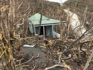
These design guidelines were produced in the aftermath of Hurricane Hugo, which devastated the U.S. Virgin Islands in September of 1989.
They are intended to be used as a guide to provide the general public with more information on building design and hurricanes and to foster the construction of structures which are better capable of withstanding hurricane force winds. The information in this booklet is provided for reference only. It is strongly recommended that anyone constructing or undertaking major repairs to a building should consult with their local architect for professional guidance before proceeding.
Hurricane Hugo has given us many lessons in building design. As we travel about the islands “reading” the damaged and non-damaged structures several observations surface and are worth repeating.
On St. Thomas, which was spared the full fury of the storm, winds are reported to have been a constant 130 to 135 MPH with reportedly documented gusts of 185 MPH. Observation of damage patterns also indicates that there were possibly tornadoes localized within the storm. Except in tornado zones it appears, on St. Thomas, that as a generalization the buildings which were well built with sufficient anchorage systems survived and the buildings which were not so well built blew away. On St. Croix, which experienced the full force of the wind with gusts above 200 MPH, such a generalization is harder to make. The whole island suffered devastation. The buildings that survived were both lucky and well built.
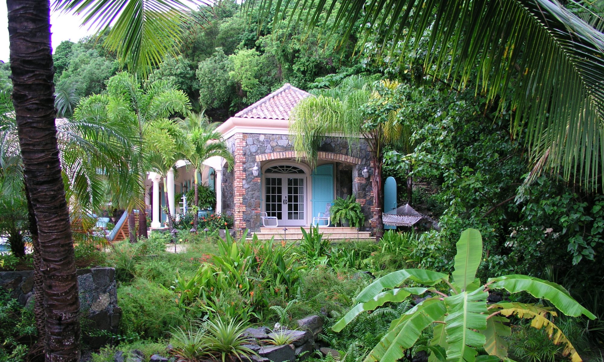
One building type rises out of the destruction as a winner against the storm and that is Traditional West Indian architecture. Both wooden and masonry traditional buildings survived the storm with minimal damage. The reasons for this will be discussed here in detail.
The building type, which, by observation, suffered the most damage, is the rigid frame, large span metal warehouse type of structure. These buildings are relatively less expensive to build, when compared with conventional construction and provide very large, unencumbered spaces within. Their negative quality is that they tend to be more susceptible to damage from high winds than conventional structures. Consideration should be given to increasing wind design loads and “x” bracing requirements when designing these structure for use in the Virgin Islands.
Download the Green Building Checklist
LESSONS FROM TRADITIONAL WEST INDIAN ARCHITECTURE
The architectural heritage of the Virgin Islands has its roots in the historical architecture of Northern Europe and New England due to the colonization and trading patterns starting in the seventeen century.
The first European settlers in the Caribbean built buildings that were similar to the kind of building they were used to in their homeland. These structures were not particularly suited to the tropical environment. Over the last several hundred years these buildings have been modified due to environment and climactic conditions so that they are functional in a tropical climate and we can see a “Caribbean Style” emerging with a distinct character of its own. This style of architecture, while undeniably charming, is also quite functional. Since climactic conditions have changed little over the last several hundred years this type of construction is still a valid way of building today. As we travel around the islands we see that it is these traditional buildings, that as a group, have survived the storm best.
The hip roof, with its steep pitch and four sides was originally designed and used to keep large amounts of snow from accumulating on the roof in northern winters. When transplanted to the Caribbean, the shape was retained, yet the design functions changed. The steep pitch provided a large volume of air space high in the building, which allowed the hot air to rise, and contributed to the cooling of the structure.
The four sloping sides of the roof provided minimal resistance to the wind and allowed the wind to blow over and around the roof regardless of wind direction.
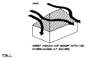
Traditional West Indian hip roofs have no overhangs. The rafters stop at the edge of the walls. This design greatly lessens the potential for the wind to get up under the eaves and lift the roof off. (Fig. 1)
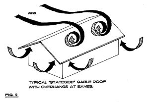
When compared with the typical “stateside, ranch type” of gable roof with its overhanging eaves and blunt ends (gables) you can see that this type of roof provides more opportunity for the wind to grab the roof around the edges and rip it
off. (Fig. 2)
Porches and galleries were added to West Indian hip roof structures as separate attached shed roofs, not connected to the main roof, to give sun and rain protection to the walls and openings. These porches and galleries are attached to the walls of the main roof and supported by columns along the outside edge, which gives them secure anchorage. (Fig. 3)
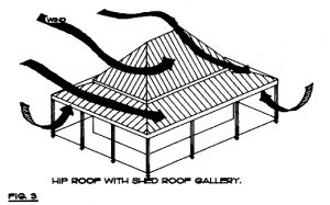
If the porches and galleries were to blow away in a storm, they could be attached so as not to take the main roof with them.
West Indian buildings also tend to have smaller, individual roofs, often as a result of the structure being built over a long period of time with additions added here and there. These smaller individual roofs do not provide as much of an airfoil for the wind to create lift as does a large monolithic roof which can act just like an airplane wing as the wind passes over it, creating a tremendous amount of lift which tends to make the roof literally to want to pop up into the sky and fly.
TRADITIONAL BUILDING MATERIALS
Both wood and masonry traditional buildings survived the storm on all three Virgin Islands.
Obviously a masonry building should be stronger than a wooden building. However, I have seen masonry structures, which were improperly constructed which collapsed, whereas properly constructed wooden structures survived. So it is important to be aware that it is not so much what material you build with, but how the whole structure is fastened together that becomes the key issue in the survival of a storm.
One of the truly amazing material lessons of hurricane Hugo is that of wood shingles. As a building covering they work amazingly well both on walls and on roofs. Again and again we have seen examples of both islands where this material is still intact. Probably it is due to the fact that if properly applied only 1/3 of the shingle is exposed to weather and 2/3 of the shingle is covered by layers of shingles above it.
Traditional wooden buildings survived the storm amazingly well. The typical wooden West Indian building has a post and beam wall system where the top and bottom plates are securely notched or tied to the studs. 4×4 studs are typically 3′-0″ on center, vertically with the same size member for a top and bottom plate. This frame is strengthened by diagonal bracing (called let-in bracing) at each corner. Properly installed let-in bracing is a major key to the survival of wooden structures. The exterior of the frame is then sheathed in wood siding or wooden T&G boards with shingles applied over it. This produces a very strong wooden box, which if properly attached to its foundation and its roof, can survive such a storm.
CONSTRUCTION TECHNIQUES: ANCHORAGE IS THE KEY
The basic concept for properly securing a structure to withstand hurricane force winds is very simple. Every major component of the structural system must be securely tied to each other and to the foundation so that there is a direct structural link between the roof and the ground.
Structural failure will occur first in the weakest link in this chain. Once failure occurs in one part of the structure then the domino theory comes into effect, and other adjacent parts of the structure begin to fall. Quite often we have seen indications that the buildings themselves appear to withstand the storm until hit by debris from adjacent buildings which then triggered the destructive chain reaction.
The following discussion will take you through some typical ways of developing anchorage systems within wood and masonry buildings.
Galvanized corrugated metal roofing has proven a good material to survive storms. Some of the following observations should be taken into account when installing galvanized roofing. (See guide specifications on back cover). In situations where galvanized roofing has blown off and left the wooden framing intact, it appears that it is the perlins to which the galvanized is nailed that is breaking away from the wooden rafters. Since wood rafters in this type of construction can be spaced as far apart as three feet it is recommended that these perlins be lag bolted (with a minimum of one 3/8″ x5″ lag bolt in each rafter) as well as nailed to the rafters. The galvanized roof is then screwed to the perlins. (Fig. 4)

In wooden framed roofs the end of the rafters should be strapped (with a 12 Ga. Galvanized metal hurricane strap) from the top of the rafter to the top  plate if the plate is attached to a concrete ring beam, (Fig. 5) or directly to the underside of the top plate for a wood frame wall (or preferably directly to the studs where spacing allows.). (Fig. 6)

 Traditional Danish West Indian hip roofs are constructed with truss rafters. A truss rafter is simply two rafters connected with a collar beam. (Fig. 7) On a small hip roof (a maximum of 18 feet wide and 30 feet long) every other rafter has a collar beam with a collar beam at the hip tying the center hip rafter collar beam into the common rafter collar beams
 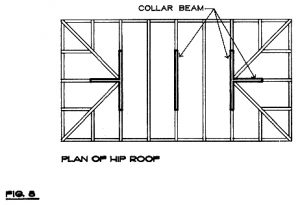 (Fig. 8). This roof usually has rafters spaced at a maximum of three feet and is sheathed in 1×6 tongue and groove boards on top of which is a layer of #15 roofing felt. The 2×4 perlins to which the galvanized roofing is screwed are applied on top of the felt and nailed and bolted to the rafters below. There is no ridge beam in this type of construction and literally hundreds of these roofs survived the storm.
In larger hip roofs, especially in older historical structures the system of bracing and collar beam usage can become quite extensive. In fact, I have inspected some structures that are so complex that it is difficult to conceive how they were constructed in the first place.
Walls are the connecting link that anchors the roof to the floor and during a hurricane they act totally opposite in the kinds of function they perform and the kind of forces they encounter.
 Normally walls hold the roof up. During a hurricane, if you are going to keep it, they must hold the roof down. It is therefore important to be aware of the tensile forces, which stress walls during a storm. It is also important to be aware of the lateral loads (wind loads) which act on walls during a storm (Fig. 9)
GUIDE SPECIFICATIONS – WOODEN WALLS
As with roofs, all components of the wall system must be securely tied together. If you are dealing with wooden walls, the bottom plates should be strapped to the studs and securely attached to the floor. If you are dealing with a wood frame floor, the studs should be strapped directly to the floor joists every three feet. If you are attaching wood frame walls to a concrete slab or masonry foundation wall, the bottom plate should be attached with anchor bolts set into the concrete every three feet on center. The wooden wall structure, once strapped top and bottom to the connecting members must then be braced for wind loads with diagonal let-in bracing set in opposite directions at each end of the wall. This frame can then be covered with its interior and exterior skin, be it wood siding or metal lathe and plaster, all of which have the capabilities of withstanding hurricane force winds if the interior framing is properly secured to its adjacent members. (Fig. 10)

MASONRY WALLS
Masonry walls, although considerably stronger than wooden walls are still subject to similar concepts of anchorage and reinforcement as are wooden walls.
If masonry walls are not reinforced with a concrete and steel re-bar skeleton they are vulnerable to collapse in hurricane force winds. The masonry wall must be reinforced from top to bottom. Masonry walls are generally supported on concrete slabs or foundations. A #4 steel re-bar should be left extending up 16″ from the floor slab at 16″ o.c. As the concrete blocks are placed in the wall the block holes containing the re-bars should be filled in with concrete. Every 48″ a #4 re-bar should extend vertically and the block cells around it filled with  concrete to the height of the 12″ deep x 8″ wide ring beam, which runs around the perimeter of the building at the top of the wall. All window and door openings should have 2 #4 re-bars extending vertically, filled with concrete on each side of the opening. (Fig. 11)
Anchor bolts should be set in the concrete ring beam, at a minimum of 48″ o.c. to attach the wooden top plate.
One system of anchorage of wooden roof members to masonry walls is shown in Fig. 5. Another system, commonly used in the Virgin islands is to have the wooden roof joists cast into the concrete ring beam so that the top of the joist and the top of the ring beam are level with each other. This can work well if the joists are anchored to the ring beam. One method of achieving this is to cast the ring beam in two parts. The lower part contains the typical reinforcing  required for the ring beam. The joists are then set on top of this and a hole is drilled trough the joist and a #4 re-bar extended through the joist. This re-bar is also attached to another re-bar projecting from the lower portion of the ring beam. The remainder of the ring beam is poured around the steel reinforcing and the wood joist. (Fig. 12)
FOUNDATIONS
Most foundations in the Virgin Islands are poured concrete and are usually integrally related to cistern construction thus making a massive base to which the rest of the structure is attached. The key element here is to again stress the importance of securely anchoring the building to the foundations. When anchoring wooden and masonry walls to concrete labs and foundations, anchor the walls every three to four feet (maximum) with a steel connector (anchor bolt or re-bar) from the wall to the foundation.
COLUMN BASES AND SHED ROOFS
The type of column base used plays a major part in the anchorage system of shed roofs. As a result of this storm I have some very specific recommendations as to the type of column bases which should and should not be used.
Recommended bases: Manufacturers names are only used for ease in identifying types of products. Any similar base produced by other manufacturers is also suitable. Types of bases recommended are integral units, which are cast into concrete with a minimum of 12 Ga. with a 7 Ga. thickness in high wind exposure areas.
 Two such examples are Simpson CB Series Column Base and Simpson EPB Series Elevated Post Bases. Columns should be bolted through these bases (Fig. 13)
NOT recommended is the adjustable type post base, which is attached to an anchor bolt set in the slab after it has been poured. These post bases have failed in hurricane force  winds in two ways: 1. The metal post base pulls out of the anchor bolt and is carried away along with the column and roof. 2. The anchor bolt shears off at the concrete and the column is carried away. Unfortunately, many times in the past, this type of connector is the only type available on the island. I would strongly urge building suppliers to discontinue stocking this type of post base altogether. (Fig. 14)
SHED ROOFS
The basic concept behind the shed roofs in relation to the main roof before Hugo was that of a breakaway roof. That is to say that conceptually the shed roof would be blown away and the main roof would stay intact. Hurricane Hugo has proven the strength of the shed roof. Many shed roofs of traditional design have survived the storm. The breakaway theory has therefore become less applicable to shed roof design.
The principal loss of shed roofs that I have observed has been from the failure of the post base connectors, which has been discussed.
 In conjunction with this failure, as the shed roof blows away, its connection to the flashing between the galvanized shed and main roof becomes a significant detail. This flashing connection should be constructed as a true breakaway detail. Should the shed roof go, its tendency to take the galvanized from the main roof with it would not be as great. The following untested detail (Fig. 15) is offered as an option to mitigate this possibility.
